Journey with Confidence RV GPS App RV Trip Planner RV LIFE Campground Reviews RV Maintenance Take a Speed Test Free 7 Day Trial ×
RV Trip Planning Discussions

Go Back   iRV2 Forums > RV SYSTEMS AND TECHNOLOGIES FORUMS > RV Systems & Appliances
Click Here to Login
Register FilesVendors Registry Blogs FAQ Community Calendar Today's Posts Search Log in
Join iRV2 Today

Mission Statement: Supporting thoughtful exchange of knowledge, values and experience among RV enthusiasts.
Reply
  This discussion is proudly sponsored by:
Please support our sponsors and let them know you heard about their products on iRV2
 
Thread Tools Search this Thread Display Modes
 
Old 08-24-2011, 09:45 PM   #1
Junior Member
 
Join Date: Aug 2011
Posts: 24
Need schematic drawing of Onan 300-3763 circuit board

Hey all you loafers out there! I need some experience thrown my way if anybody can help I sure would apprciate it...

I've got an Onan (89') model NHE Spec E genset (6.5KW) that someone's already removed the oem board and installed a newer version 300-3763 board. I'm trying to follow the circuits but don't have any thing on this newer board... I'm trying to interface the service manual wiring diagram of mine (OEM) to this newer style board... I've got only 9vdc going to the fuel pump relay and a very weak spark when trying to start it, looking at my OEM manual, it looks like the fuel pump and ignition circuits are comming out of this board and not the volt regulator.... but I'd like to see the schematic first to verify my train of thought.

If anyone can tell me where to find this one wiring diagram... I would be eternally grateful!

Thanks Y'all!
mrtinker is offline   Reply With Quote
Join the #1 RV Forum Today - It's Totally Free!

iRV2.com RV Community - Are you about to start a new improvement on your RV or need some help with some maintenance? Do you need advice on what products to buy? Or maybe you can give others some advice? No matter where you fit in you'll find that iRV2 is a great community to join. Best of all it's totally FREE!

You are currently viewing our boards as a guest so you have limited access to our community. Please take the time to register and you will gain a lot of great new features including; the ability to participate in discussions, network with other RV owners, see fewer ads, upload photographs, create an RV blog, send private messages and so much, much more!

Old 08-25-2011, 08:48 AM   #2
Senior Member
 
Dave78Chief's Avatar
 
Join Date: Jun 2009
Posts: 1,528
Based on a little web research, I can see why you have a bit of confussion. Not sure if you have seen all this so (and for anyone elses benifit):

Web site of someone who has performed the 300-3763 upgrade:
Onan NHE Control Board Update Issues

The Onan 300-3950 Upgrade Instruction sheet that installs the 300-3763 Control board:
http://www.spaco.org/onan/3003950Kit.pdf

The current Onan Service Manual that is used to support the NHE generator:
http://www.cumminsonan.com/www/pdf/manuals/965-0528.pdf

In that last document, you will find the SPEC J wiring diagram on pdf page 151 (Manual page B-2; Onan drawing 611-1206) which should be the schematic for a 300-3763 board. The 300-3763 control board was implemented at spec H. Given that that drawing is based on an electronic ignition style setup, you will have to adapt it to your Spec E points based system like described in the "Here are the Differences" section of the 3950 upgrade site above. A description of how the control board operates (based on the schematic) starts on page 97 (Section 7) of that document. 300-3763 Control board checkout starts on pdf page 147 (manual page A-9).

You need to know if the low voltage is during start and run or if it is only low during the start phase, or during the run phase. Different paths through the board are used for each portion.

Good luck,
Dave
Dave78Chief is offline   Reply With Quote
Old 08-27-2011, 06:48 PM   #3
Junior Member
 
Join Date: Aug 2011
Posts: 24
R7 (Fuel Pump external resistor) looks damaged!

Thanks so much for the advice 
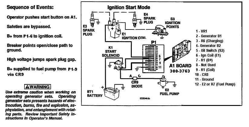
Dave78Chief. I found the schematic you referred to right away. I put another circuit board in it and still had the poor voltage to the fuel pump... 9-10vdc so I had to pull out the generator to find R6 and R7.

(See my jerry-rigged slide hammer puller to get the generator to slide out!) Looks like the ball bearings in the slide out rail mechanism is way past gone..... Does anyone know if this is repairable? (2nd pic)

Then I found R7 (1st pic)... it was a mess... I'm unsure if it was my pulling on the terminal that broke it or if it was the worn out ceramic that was already broken... but when I checked it, it had about 32Meg-ohms across it. Because the installation instructions said that "There may or may not be an external fuel pump resistor" (Control Board Update Issues)... I just jumpered out the terminals and bypassed it.... does anyone know for sure if its needed or not? I really thought that this may have been the reason I was only getting 9-10vdc to the fuel pump.

Since R6 was right next to R7, I checked it too.. the terminals/wires looked good.... I measured 5.3 ohms across it. (No pic's of this one, looks just like R7, just smaller)

I also checked CR9, (3rd pic) the diode controlling the power flow once the generator output is up, it appears to be working but my readings I thought were a bit high... 3.7 Meg ohms (when conducting) and Infinity when reverse biased.
After many minutes of frustration, I checked the voltage at the starter solenoid... it dropped to 10vdc whenever I was trying to start.... Wa-Lah! (the light bulb came on!) At first thought, I figured there was a cable terminal or connection bad leading back to the generator. But then I checked the battery... its voltage dropped to the same 9-10vdc too! (I'm thinking now...."Bad, bad, bad, battery!)

To make a long story short, I used my AGM trailer 12v battery in parallell with the coach battery and connected it with jumper cables... the fuel pump still had less than 12vdc to it but now it kicked out the fuel like a pissed off copperhead would spit its venom....and I was only reading about 10.5vdc to the fuel pump now! Even so, the Generator kicked over and ran like a champ after that.... I think the coach battery is going bad (I have no test equip to do proper load test or specific gravity test) and or the cables/connections/battery isolation relays are dropping the 2vdc somewhere along the way probably due to high resistance. Anyway, its running now. It even starts without the parallell battery. I just hope it stays that way....

One question I still have though is should I replace the R7 wirewound resistor or just leave it bypassed?

Thanks again for the help y'all!
Attached Thumbnails
Click image for larger version

Name:	1314373247528.jpg
Views:	631
Size:	46.5 KB
ID:	13344   Click image for larger version

Name:	1314375353018.jpg
Views:	776
Size:	19.2 KB
ID:	13345  

Click image for larger version

Name:	1314373234128.jpg
Views:	665
Size:	19.0 KB
ID:	13346  
mrtinker is offline   Reply With Quote
Old 08-28-2011, 12:08 PM   #4
Senior Member
 
Dave78Chief's Avatar
 
Join Date: Jun 2009
Posts: 1,528
Onan made a mess of this one! Anyway, the key for you is pdf pages 141-142 (manual pages A-3/4). However, the A1 board on those pages is based on the original 3056 board. All pinouts have to be remapped to the new 3763 board based on the upgrade instruction. Even so all of that information is based on a points based system that has the R-7 Fuel pump resistor that you shorted out (Onan P/N 304-0798 from Onan Parts book 940-0228). The R-6 resistor (Onan P/N 304-0794) is used for battery charging. So far I have not found anything that says what the value of either resistor is. Maybe some of the RV Techs here know what they are. I will work up a remap of the A-3/4 pages to the new board and post drawings later. I have to run out for a bit.

Dave
Dave78Chief is offline   Reply With Quote
Old 08-28-2011, 07:36 PM   #5
Senior Member
 
Dave78Chief's Avatar
 
Join Date: Jun 2009
Posts: 1,528
Here are the reworked Functional diagrams (page A-3 and A-4) that reflect a points based NHE Spec E/F that have a voltage regulator (VR1) and have the A1 board updated to a 300-3763 version by Onan upgrade 300-3950. The pre modification wiring diagram is located on pdf page 106 (Page 8-4). While I updated these drawings based on the modification information, I have not found a wiring diagram that reflects the post upgrade configuration.


Dave
Dave78Chief is offline   Reply With Quote
Old 08-28-2011, 11:16 PM   #6
Junior Member
 
Join Date: Aug 2011
Posts: 24
I still have a question?

So, what's R7 doing in the circuit? Lowering the voltage and amperage (Watts) through the fuel pump in the "Run" mode? Maybe they designed the power to the fuel pump be less when the generator is running than when its starting?

Remember, I was only getting 9-10 vdc to the pump when it was trying to start... Then after I jumped out R7 it didn't make any difference. I got the pump to take off after I put the additional 12v battery in parallell with the coach battery, I checked the voltage but it still was only about 10.5vdc but I don't remember if the gen was running or not when I checked it then.....

At this point I'm just wondering if I should replace the resistor (R7) or not... Knowing why its there would tickle me to know but I just wanna get past this now...

Thanks for all your hard work trying to explain this to me Dave!
mrtinker is offline   Reply With Quote
Old 08-28-2011, 11:32 PM   #7
Junior Member
 
Join Date: Aug 2011
Posts: 24
Just takin another quick look at the Speck J schematic with the 3763 board (Page B-2) it doesn't even have the R7 resistor depicted in the circuits.... go figur???
mrtinker is offline   Reply With Quote
Old 08-29-2011, 04:37 AM   #8
Senior Member
 
Dave78Chief's Avatar
 
Join Date: Jun 2009
Posts: 1,528
Spec G and above used a different type of Fuel Pump so R7 may not be needed with them. R7 acts as a current limiting resistor so yes there would be a voltage drop across it. My guess is that it was used to limit how strong the fuel pump worked (PSI reduction). R7 is not expensive and replacing it would be the best approach. Better safe than sorry. I was not able to find what value R7 was supposed to be.

Dave
Dave78Chief is offline   Reply With Quote
Old 08-29-2011, 03:48 PM   #9
Junior Member
 
Join Date: Aug 2011
Posts: 24
I orderd it today... and a few other parts too... I'll let y'all know what the resistance value is before I put the new resistor in it.

Thanks again for your help Dave!
mrtinker is offline   Reply With Quote
Old 09-06-2011, 07:01 PM   #10
Junior Member
 
Join Date: Aug 2011
Posts: 24
Just thought I'd update this thread as well... I talked to the Onan Genset manuf. rep's this week... Turns out that diode "CR9" isn't a part they carry anymore... seems there wasn't enough "turnover" to justify making any more of them or something to that effect....

I was reading "infinity" and then "3.2Meg Ohms" across the terminals when testing it... Anybody out there who can verify these readings with me?

I think its kinda high on the forward bias reading... but I did get the genset to run again and seems to be operating the fuel pump just fine.

Note: There's two fuel pumps inline with this genset.... one was bad (the round one attached to the genset) and clogged up.... I'm not sure if it ever worked like this but this was how I got it and ended up figurin it out.... it was a real mess!
Attached Thumbnails
Click image for larger version

Name:	89' Eurocoach (2).jpg
Views:	2221
Size:	301.0 KB
ID:	13623   Click image for larger version

Name:	2011-08-26_11-40-32_615.jpg
Views:	558
Size:	513.7 KB
ID:	13624  

mrtinker is offline   Reply With Quote
Old 09-06-2011, 08:21 PM   #11
Senior Member
 
Dave78Chief's Avatar
 
Join Date: Jun 2009
Posts: 1,528
If the unit is starting up without any problem, then you can stop worrying about CR9. It is ONLY used during starting. If it was open then the unit would not start. If it was shorted then the fuel pump would run constantly.
Now I may confuse you to all end but if you understand basic electronics:
Refer to Figure 8-2. When you depress the START switch the K4 Start relay is energized. Voltage flows from the battery through F1 straight downand makes a U turn up through the K4 contacts which are now closed (K4 energized). It continues on down through CR2 then through CR9 to the fuel pump (E2). When the engine starts, and the generator starts generating electricity, DC voltage is produced by the CR1 bridge rectifier assembly and thereby energizing K2. When K2 energizes it results in de-energizing the K4 relay (normally closed K2 contacts on the topside of K4 are opened). Now, because the engine is running, the oil pressure switch (S2) closes allowing K3 to energize. So, with K4 de-energized and K3 energized, instead of the fuel pump voltage flowing through K4/CR2/CR9 path to E2, it now flows down the K3/CR3/R7 path to E2. See, it is simple!
As I said before, R7 is only used with the points based systems (pre Spec G) that used a different fuel pump.

Dave
__________________
Dave in Virginia
1978 Winnebago Chieftain
Dodge M400 - 440-3
Classic Winnebago Site: https://www.classicwinnebagos.com/forum/index.php
Dave78Chief is offline   Reply With Quote
Old 09-28-2011, 07:29 AM   #12
Junior Member
 
Join Date: Aug 2011
Posts: 24
Update on the resistors...

Thanks for the explanation! I just got around to uploading the pic's I took of the resistors that I ordered. I only replaced the smaller (R-7) resistor because the larger one (R-6) read okay. Here they are!
R-6 (Larger) = 5.2 ohms
R-7 (Smaller) = 1.7 ohms
Attached Thumbnails
Click image for larger version

Name:	2011-09-18_10-48-29_656.jpg
Views:	517
Size:	375.7 KB
ID:	14307   Click image for larger version

Name:	2011-09-18_10-48-55_776.jpg
Views:	459
Size:	374.0 KB
ID:	14308  

mrtinker is offline   Reply With Quote
Old 02-20-2014, 09:28 AM   #13
Junior Member
 
Join Date: Feb 2014
Posts: 1
I have an interesting problem, my generator wants to start no matter what. I have to pull the fuse to keep it from running. I'm am very mechanically inclined, but new to motorhomes. any suggestions on what could be the problem?
johnrwhitt is offline   Reply With Quote
Reply

Tags
onan


Currently Active Users Viewing This Thread: 1 (0 members and 1 guests)
 

Posting Rules
You may not post new threads
You may not post replies
You may not post attachments
You may not edit your posts

BB code is On
Smilies are On
[IMG] code is On
HTML code is Off
Trackbacks are Off
Pingbacks are Off
Refbacks are Off


Similar Threads
Thread Thread Starter Forum Replies Last Post
Onan BGE charging circuit JAMESRAYSR Vintage RV's 5 11-16-2010 04:46 PM
Triple Slide-Out Control Board Dr4Film Monaco Owner's Forum 2 07-29-2010 11:30 PM
Front Electrical Circuit Board DCTENT Monaco Owner's Forum 0 09-09-2009 09:24 AM
Monaco Circuit Board Supplier MegaRV Monaco Owner's Forum 3 03-05-2009 04:47 PM
Power Distribution System Board Replacement Mike H 2002 Revolution MH-General Discussions & Problems 4 01-24-2008 02:46 PM

» Featured Campgrounds

Reviews provided by


All times are GMT -6. The time now is 07:10 AM.


Powered by vBulletin® Version 3.8.8 Beta 1
Copyright ©2000 - 2024, vBulletin Solutions, Inc.